Last month we interviewed Steven Boze, concept designer at US Marine who is using 3D laser scanning to improve the design and manufacturability of the company’s Bayliner, Trophy and Maxum lines. Boze spent 12 years as master plug builder and six years in the company’s mockup department. He is responsible for all physical prototypes for the group.
US Marine designs and manufactures boats ranging from 16-foot recreational boats to 57-foot motor yachts. It is a unit of the Brunswick Boat Group, Knoxville, Tenn., which is part of the $5.2 billion Brunswick Corporation, a leading manufacturer of marine engines, pleasure boats, fitness equipment, bowling and billiards as well as emerging technologies.
Dimensional control for boat building
To build boats in production volumes that range from a few units to a few thousand units, US Marine first models the boat with its UGS Corporation UG NX CAD system. The CAD geometry is used to mill a plug from a foam-covered frame. The plug is then used to make a fiberglass mold which in turn is used to make individual hulls, decks and liners. For higher production runs, the process is repeated one more time to make a glass master and then a production mold.
According to Boze, the dimensional control issue is that fiberglass always shrinks when it cures – the end product is smaller than the mold. “Shrinkage of 5-10mm is not uncommon. Shrinkage can also vary in different directions,” explains Boze. He is on a mission to build a database that quantifies the shrinkage for a cross section of the company’s product line – the results will be applicable to the complete product line of some 75 different boat models. Determining exactly how much shrinkage to allow is part of the art of mold design – 3D laser scanning is bringing engineering discipline to this art.
In addition, laser scanning allows the concept design team to reverse-engineer modifications that may be made to early-stage physical prototypes. When the team is satisfied with a layout, they can scan the modified tooling and get the modifications back into the master design model.
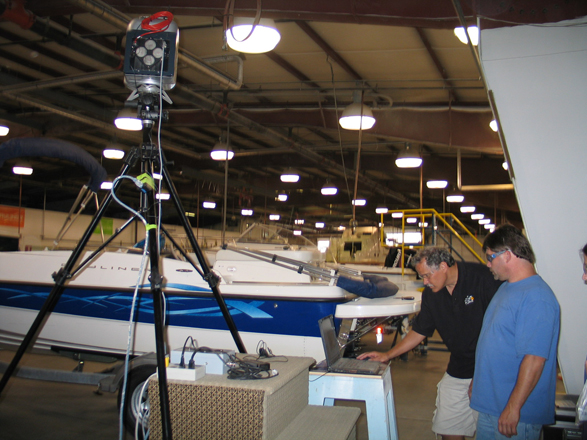
Manufacturing companies have been using laser scanning to reverse-engineer components for years – typically at short distances for small components. What is particularly interesting about US Marine’s scanning is that the scanned parts can be as long as 15 to 60 feet. All scanning equipment choices require making tradeoffs between cost, speed of acquisition, dynamic range and resolution. Terrestrial laser scanners have a valuable role to play for some product tooling and equipment metrology applications where length scales can be 10 to 100 feet and the needed accuracy is of order of 1/4 inch or less.
Business drivers for getting accurate dimensional data
Dimensional variation between design geometry and actual product geometry can impact the business by making assembly of the hull and deck difficult. Sometimes the issue is aesthetic – trim pieces may not fit if the fiberglass parts are too large or too small. Molds also have to be modified to accommodate changes to installed equipment, which can range from a coffee pot, to an oil filter on a diesel engine, to a propeller mounting strut.
“US Marine is striving to use a digital master model from concept design all the way to customer service,” says Boze. To get there requires high confidence in the geometry. The issue is more than shrinking fiberglass – often 3D CAD geometry of purchased assemblies does not exist or is unreliable. Even when the component part geometry is well known, the assembly geometry – e.g., whether the newly sourced oil filter can fit on the new bracket – can be incomplete, which means a potential service issue if the service technicians can’t reach the dipstick on the installed engine as a consequence. geovisit();geovisit();
Laser scanning work process
Boze’s team of four uses a Trimble GS200 laser scanner purchased from Digital Technologies Inc., Seattle, Wash., to scan plugs, molds, finished hulls as well as equipment to be installed. Bob Francis, president of Digital Technologies, was part of the team responsible for evaluating reverse-engineering technologies for US Marine.
The point cloud data (PCD) is captured with PointScape (the operating software for GS200), then processed with Trimble’s RealWorksSurvey application, then exported to UGS’s Imageware application, where it is processed in order to be read into UG NX. Once the processed PCD is inside UG NX, offset analysis against the original design model can be performed on a selective, as-required basis.
Typically data sets range from hundreds of thousands of points to millions of points, which Boze says gives him the required density. “Doing the work with in-house resources brings flexibility and agility to the work process as well as cost benefits,” says Boze. “Using the same in-house software from project to project also brings consistency to the process.”
Technical challenges
Boze would like to see scanners improve in their ability to capture surfaces that are both black and glossy. The current workaround is to coat or spray the surfaces to be scanned to conform reflectivity to the scanner capabilities. “It would be useful to be able to capture data at ranges shorter than 3m in order to set up inside the molds,” Boze adds.
Registering scan data with the original CAD model is more difficult and less straightforward than Boze believes it should be. He expects this process to improve as his team becomes more experienced. Part of the solution lies in improving UG NX’s capability to manipulate PCD data directly. Boze says he’s a big fan of UG NX – its intuitive user interface makes it his favorite CAD tool, and he expects the PCD capabilities to improve in time. He’d like to see Imageware functionality embedded inside UG NX to eliminate one import/export step.
As part of the procurement process, the US Marine team evaluated Rhino from Robert McNeel & Associates, Seattle, Wash., as well as Geomagic from Raindrop Geomagic, Inc., Research Triangle Park, N.C. The tight integration of Imageware with UG NX gave the nod to Imageware.
Manual alternative
The alternative to laser scanning is to take the lines off using a plumb bob, tape measure and a notebook to capture the data. According to Boze, this process, though accurate enough, is extremely time-consuming and, in the end, the points still must be entered into a lofting application to yield a digital representation of the structure.
Laser scanning enables digital master model
Five years ago, US Marine built all of the plugs for its boats by hand. The vision for new product development is to use a master digital model all the way from prototype development to customer service. To accommodate change, it is essential to have high confidence in the as-manufactured geometry. Says Boze, “Little things add up…If our engine supplier changes a mounting bracket for a water pump, production might find an interference at assembly. If the real world does not equal what it is in our model, we have a problem. The goal is to determine fit digitally before we make the molds or make changes to existing molds.”
About Brunswick Boat Group
Headquartered in Knoxville, Tenn., the Brunswick Boat Group is the largest maker of pleasure boats in the world. Net sales in 2004 were $2.3 billion. The Boat Group makes Albemarle, Baja, Bayliner, Boston Whaler, Crestliner, HarrisKayot, Hatteras, Lowe, Lund, Maxum, Meridian, Palmetto, Princecraft, Sea Boss, Sea Pro, Sea Ray, Sealine, Triton and Trophy boats; Attwood marine parts and accessories; Land ‘N’ Sea and Kellogg Marine marine parts and accessories distributors.
About Digital Technologies Inc.
Founded in 1998 by principal Robert Francis, Digital Technologies Inc., Seattle, Wash., provides systems and services for reverse engineering and industrial metrology to aerospace, marine and other manufacturing companies as well as civil engineering firms. Francis’s background is in aerospace product development and he reports he draws upon 20 years of experience to transfer digital engineering technologies know-how to his customers. geovisit();geovisit();


