

Look back through history. Surveying instruments observe and measure our surroundings, much in the same manner we do. However, instead of simply committing these observations to memory, like we can, they were recorded on a physical medium: stone or clay tablets, scrolls, parchment, paper, and, more recently, in the digital domain.
A transit or theodolite emulates the human instrument: level vials acting like our inner ear, plumbing to the ground, and horizontal and vertical axes of our necks and eyes. We can judge distance, while only coarsely, through stereovision and visual cues, so when using legacy instruments, we mainly relied on external tools to measure distance (e.g., chains and tapes).
Fast forward to the era of reality capture, particularly multi-sensor instruments, we have all but abandoned external measurement tools. In the modern digital era, Electronic Distance Measurement (EDM) lasers, and in some cases photogrammetric techniques, provide ranging. Plus, mimicking and surpassing what our inner ears can do, relative movement is detected via Inertial Measurement Units (IMU) and electronic accelerometers.
We are now, ironically, employing technologies and techniques that more closely mimic how humans perceive spaces, achieving dizzying levels of precision, accuracy, and reliability that we cannot. What we can see, reality capture instruments can see—but so much more—recorded as rich 3D models.
Progressive observation techniques fuel modern reality capture, as performed with mobile mapping systems, handhelds, backpacks, UAVs, or with terrestrial laser scanners (through overlapping setups). The principles of resection, and intersection are fundamental to legacy static methods: observing points from different vantage points and observing multiple points from each vantage point. Reality capture is also performing intersection and resection, but in some cases, it is done many thousands of times per second as the instrument moves. This also enables techniques to determine the quality and spatial fidelity of observations on the fly—movement providing stability.
Sensory Cues
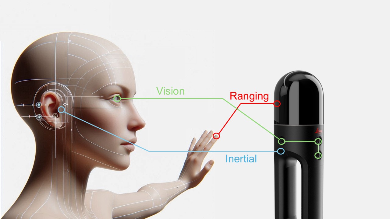
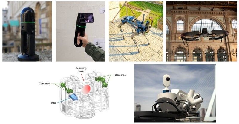
“If humans move towards a building in our field of view, it gets larger. If we move to the left, then the building moves to the right—this is how we perceive this movement,” said Dr. Bernhard Metzler Director Technology, Reality Capture Division at Leica Geosystems part of Hexagon, a leader in reality capture sensors and software. “What we do with [vision-based spatial positioning] algorithms, they are detecting these features, specific well-defined points, and it's tracking from one frame in the camera to the other, how these features move in the field of view.”
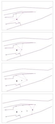
An instrument progresses along an irregular corridor (above right, Metzler). Cameras recognize features as points in all directions. As the instrument moves, resection is performed using these points, providing a real time position. This technique of Visual SLAM is used in multiple Leica Geosystems reality capture sensors (and in some instances, combined with lidar SLAM, dubbed “GrandSLAM”). (Metzler)
“If you walk toward something, you see that all the visual features are moving to the outside, which means the object is getting larger (above, Metzler), if they are moving to the inside, then you are walking away, and the object gets smaller. If we turn our head to the right, the features move left.” said Metzler. Humans, robots, and reality capture systems leverage these observations to determine "ego-motion" (motion of a sensor relative to an environment) from which the relative positions of subsequently observed features can be determined.
"Say that we turn out the lights, how do you measure the space?" said Metzler. "You reach out and touch the walls. This is what laser scanners do only with light. It is like a huge octopus with arms in all directions. The light is now touching, fore, left, right, in all directions. If you move forward, the distance to the objects ahead decreases, and the distance in the back increases. This is the basics of the technology.”
If the instrument is moving, as in SLAM (Simultaneous Localization and Mapping), algorithms can seek patterns in captured geometries, as they move along, to define features with high confidence from multiple vantage points.
Dynamic Positioning
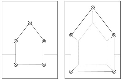
Features can be defined with great precision relative to the position of the camera and/or laser scanner. But where is that position in space? With a total station or theodolite, you can perform a traverse; a series of observations connected to established control points, and/or closing a traverse in a loop (on itself) to mathematically determine the error of closure, and the precision and accuracy of each point. However, this is only practical for a limited number of points, compared to reality capture instruments—hundreds of points compared to thousands or millions of points.
For terrestrial laser scanner (TLS) capture, the answer can be simple resection or intersection. Some scanners, like the survey-grade Leica ScanStation P40 can traverse; you sight control points ahead and behind the instrument as you move it from setup to setup. SLAM scanners, in contrast, may rely on the IMU to determine position, while patterns in the scanned points are compared to previously captured points, on the fly, to create a point cloud as it moves. This provides a live preview of what you have captured, which helps you determine completeness and if you need to fill in certain areas.
However, IMU are subject to drift, so it is not optimal as a singular positioning mechanism if you are seeking high precision and accuracy. For many SLAM systems, you need to close the observation session back to where it began, like in a closed traverse loop. By doing so, the observations can be post-processed to determine the error of closure and spread that error out among all observations via an adjustment
An instrument progresses along an irregular corridor (below left, Metzler). Each dome scan determines the geometry, matching, and confirming with the geometry determined by each successive scan. In this example, a Leica BLK2GO is performing a full done scan as many as 5 times per second, or at a normal walking pace, about every 20 centimeters.
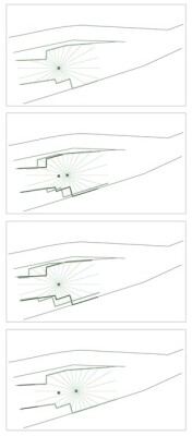
“Lidar SLAM is a different concept than Visual SLAM. With lidar SLAM, we can do a fast full dome scan as frequently as five per second, mapping the geometry,” said Metzler. This is between 300,000 and 360,000 points per second. At normal walking speed, this is about twenty centimeters between scans. “If we now move and scan again, then we detect that there is a shift between what we scanned before, between our map and the current scan. We just match the new full-dome scan with the previous one, and what fits together—is just compensating for our motion. That is basically how lidar SLAM works; it's a minimization of the distance between the corresponding points of current scan and the previous one. This is very similar to point cloud registration. But it is not done once, instead, we do it every 20 centimeters.”
Metzler also pointed out a weakness in SLAM when determining ego-motion: "Lidar SLAM needs geometry. If you are, for instance, in a tunnel, and you cannot scan the front or the end because it is cylindrical shaped. Fixing the degree of freedom along this tunnel is difficult because it's just a cylinder.”
There are more advanced ways of leveraging human spatial modalities directly into reality capture processes, on the fly, which can overcome many of the challenges of standalone IMU, lidar, or imaging positioning.

“We introduced a Visual Inertial System, which we call VIS when we released the Leica RTC360," said Metzler (left). "When you set up to do a scan, there are five cameras that look for features all around, and when you move to the next scan setup, it looks for as many of those features as it can find, plus more ahead—resection and intersection." The RTC360 also has an IMU on board, which determines a coarse position and orientation as you pick up the instrument and move it to the following setup location. This helps speed up the interrogation of the surroundings to find those common features to use in determining resections and intersections.
Algorithms need to determine which are the optimal features to include. “We cannot fully control what points are selected, and there might be also some outliers,” said Metzler. “Then, based on some specific algorithms, we do outlier detection and rejection, so the remaining features are good enough to derive the ego-motion.”
A handheld SLAM laser scanner, like the BLK2GO, uses the onboard IMU and progressively captured points to determine the ego-motion on the fly, much like VIS. But what if you combine the two techniques with the same instrument? This is an area where reality capture is rapidly moving forward…
Multi-Sensor Systems
The BLK2GO is leveraging both Visual SLAM and lidar SLAM for positioning. Metzler says this was dubbed GrandSLAM. "The combination allows us to work in situations where one or the other might have a weakness," said Metzler. “For instance, if the room is not well lit, or if it has blank white walls, Visual SLAM alone, might not work so well.”
Lidar SLAM for positioning, as mentioned previously has weaknesses in environments that lack diverse geometry, like a long smooth tunnel or blank walled corridor. “These two technologies, Visual SLAM and lidar SLAM, complement their features,” said Metzler. “Really working together, compensating for the deficiencies of the other one. That's why GrandSLAM works so nicely.”
Combined approaches have been also applied in variants for the Leica BLK2FLY drone, and Leica BLK2GO PULSE. The BLK2GO PULSE is an interesting SLAM approach, using an array of Time-of-Flight (ToF) sensors that synchronize pulses with the onboard cameras. This enables real-time colorization of the progressively captured point clouds; many SLAM and static scanners typically only apply colour during post-processing. The Visual and lidar SLAM approaches have also been adapted for robotic reality capture in the Leica BLK ARC, which is featured in a configuration carried by the Boston Dynamics’ Spot.
Mobile mapping systems take multi-sensor dynamic positioning to a whole new level. Mounted on a vehicle, space, power, and weight are much less of an issue than with handheld or terrestrial instruments. In addition to arrays of cameras, scanning heads, GNSS, and IMUs, SLAM scanners are being added for position stabilization.
In a distinct departure from legacy systems, the Leica Pegasus TRK portfolio has added dedicated small front and rear SLAM scanners (in one or two-head configurations). These are primarily to aid the tightly coupled GNSS/IMU solution to improve the determination of ego-motion. The SLAM on the Pegasus TRK addresses the problems encountered in GNSS-limited or GNSS-denied environments, like urban canyons, under a heavy tree canopy, or in tunnels. When GNSS is interrupted for more than 60 seconds, the IMU starts to drift substantially; this SLAM integration can maintain high accuracy in those situations.
The developers determined that if you have a 360° field of view with the SLAM, you can better calculate the trajectory, so two were added. And the orientation of the SLAM scanners matter. A horizontal field of view works best for such SLAM applications. If mounted vertically, you would only see a profile for that spot; horizontal gives a wider field of view. While the front and rear scanners are primarily for positioning, all of the data is captured and could be processed into point clouds, as could images from the cameras, for instance, to fill in where something was missed by the primary scanners.
Role Models
In the near future, we expect to see Visual SLAM leveraged for other reality capture sensors. And who knows what the future might hold for reality capture from R&D into radar systems from the autonomous vehicle systems sector. Could we see radars on mobile mapping systems? Perhaps to help penetrate roadside vegetation?
Consider as well, that in addition to mimicking human sensory cues, reality capture now benefits from thinking more like humans. It was only a few decades ago that processing, classification, and analysis of reality capture data relied on classical computing approaches. Now, pattern-seeking neural network approaches have become the norm.
Humans and other living creatures are designed to spatially perceive their surroundings, which is essential for daily life and survival. We now design machines to be not only just as, but even more perceptive than us. They are designed to see better, use a wider range of sensors, see a wider spectrum, and we teach them to be much more efficient at capturing, documenting, analyzing, and modelling than we can. As the examples above show, we are off to a good start.