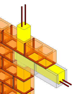
Like many building documentation service providers, my firm ARC uses a scan-to-BIM process for developing existing conditions models. Generally speaking, most of our deliverables conform to an LOD (Level of Development) 200 per the BIM Forum / AIA definition of LOD and, as such, have become a fairly standard form of deliverable for our scan-to-BIM process (see Fundamental LOD Definitions). However, I’ve noticed it is becoming a more common occurrence for clients to request higher LODs for their deliverables. Achieving an LOD greater than 200 for an existing conditions BIM can provide some significant challenges that clients are often either unaware of or not willing to consider.
One such challenge relates to the limitations imposed by the type of data we can capture with a laser scanner. Scanners are line-of-sight instruments and are not capable of seeing through objects. The resulting data capture is represented in the form of millions of measured points, or a point cloud. These points represent the geometry of objects they capture quite nicely. However, they don’t tell us what a given building assembly is comprised of. For example, the point cloud may represent a wall to the extent that we can see it is out-of-plumb and maybe by looking at the data we can make out some material characteristics such as the finish material. However, we cannot tell whether the inside of the wall is made up of wood studs, metals studs, CMU or some other material. When LOD300 or higher is needed, modeled elements are required to be represented within the Model as a specific system. This means a generic representation as allowed by LOD 200 is no longer acceptable.
The other challenge is often we cannot access concealed conditions within a building, for example, we might not be able to access above a hard lid ceiling, inside of furred columns, below ground for utilities, etc. If the building’s structure needs to be documented and shown in the model at an LOD300 or higher how can a service provider capture and represent this data? Often the process falls back to incorporating record drawing information.
Of course, concealed data incorporated from record drawings is not validated. While it may be represented in the model, without validation it cannot be confirmed as being the actual existing condition. Often a higher degree of confidence may be associated with structural elements obtained from record drawings because they are often called out with a defined size, shape and location; however MEP systems are often drawn schematically and are rarely dimensioned. Using 2D drawings to represent these types of systems accurately in 3D can be very difficult if not impossible especially when it comes to placing them in the vertical plane.
Lifecycle models require LOD350 or greater so that actual product model numbers, closed loop systems and information on detailed fabrication can be accessed. For example, at LOD 350 for an exterior window wall the mullion sizes and shapes are to be defined along with the layouts and anchorage types. Of course a laser scanner cannot typically determine the shape of an installed aluminum mullion nor the placement or type of the anchorage elements so other investigative efforts would need to be incorporated into the process of existing conditions data capture.
This is a very big topic that requires a lot of discussion up front if the team expects to receive a useable deliverable. “Intent defines process”: Having a clear definition of intent will help the service provider recommend a process that can achieve the desired results. When it comes to existing conditions building documentation it is important to realize that even though a given LOD may be specified, there are limitations to what can be documented and represented. The further we get from a Geometric BIM (LOD200) and the closer we get to a Design or Lifecyle BIM (LOD300+) the less likely we will be able to validate everything that is being represented.


